Artisan Glove
Artisan Glove is a sensing-glove design for recording hand contact, vibration and video.
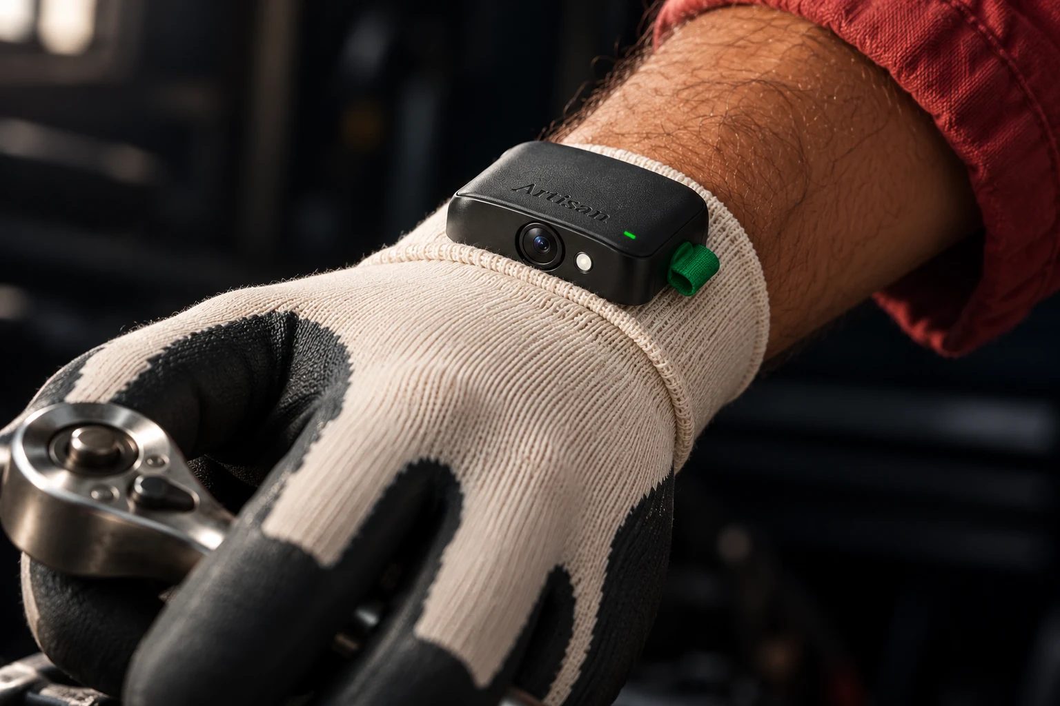
I designed a glove and cuff to put contact, vibration, motion and footage into the same recording workflow. The V4 engineering includes twenty pressure sites, twenty PVDF channels, two IMUs, an ESP32-S3, a cuff camera and SD recording. The source brings together the sensing stack, circuits, enclosure, acquisition firmware and browser inspection tools.
Who it helps
Embedded hardware developers and researchers recording hand interactions, who want editable engineering and a reproducible software starting point.
The problem
A video shows the hand's movement. Contact, vibration and motion readings add the physical signals around that interaction. Recording and inspecting those signals together requires sensing, acquisition, storage and a useful way to inspect the result.
Product areas
Sensing locations
Twenty pressure sites and twenty separate PVDF vibration channels form the hand-sensing design. Two IMUs provide motion readings at the cuff and hand.
Cuff and electronics
The native enclosure viewer contains 48 generated parts, 561 main-board component envelopes and a separate hand IMU tile. Choose Assembled, Open or Exploded and select a component to inspect its placement. The rigid cuff measures 112 × 104 × 45.5 mm; the compact appearance concept is a separate form study.
Acquisition and recording
The ESP32-S3 source implements raw electrical acquisition, feature calculation, timestamps, labels, quality/loss flags, camera handling and SD recording paths. Host checks exercise the acquisition and packet logic. Physical timing, calibration and mixed camera/radio/SD behaviour remain part of assembled-device qualification.
Device monitor
The local browser monitor provides a contact map, camera view, selected vibration waveform and spectrum, labels and acquisition health. It waits for actual cuff data; the setup guide explains how to open it locally and connect a built device.
A complete source journey
- Open the CAD viewer, switch to Open or Exploded, and inspect the cuff and individual components.
- Follow a sensing site through the sensor stack, labelled harness, analogue front end and ADC in the native circuit files.
- Run the host checks to produce acquisition packets, then inspect them with the independent decoders.
- Open the device monitor to see where contact, camera, waveform and health data appear when a cuff is connected.
- Continue through routing, manufacturing acceptance, assembly and measured calibration using the build checklist.
Design decisions
- Keep the sensing locations on the hand and recording electronics at the cuff.
- Retain pressure, vibration, motion and visual context as separate capture inputs.
- Keep native engineering geometry and nominal fit checks alongside editable circuit and firmware source.
- Identify the compact appearance concept, the current engineering envelope and the earlier physical experiments separately.
Current state
The source beta contains a recorded ESP32-S3 compile and reproducible host checks: 34 acquisition-core, 13 HTTP, 32 protocol/piezo and nine camera cases. The native main board is an eight-layer, 100 × 80 mm design with 561 components; the canonical applied board has 20 unconnected items. Separate hand-tile manufacturing outputs are included. Physical assembled V4 qualification is pending.
Earlier Bela Mini work produced nine saved recordings and an original signal comparison. Saved-clip classification and the unsuccessful live grit-identification trial have their own experiment record. Those results belong to the earlier contact-microphone setup; V4 has a different sensing and acquisition architecture.
Continue the build
Finish main-board routing, review its saved warnings and bind the fabrication outputs to the enclosure. Obtain process acceptance, assemble the cuff and sensing harness, then measure signal calibration, cross-talk, timing, optics, camera/radio/SD load, faults and endurance on the complete unit.
Build with it
Repository guide · Setup · Architecture · Design history · Engineering status · Verification · Earlier Bela experiment